-
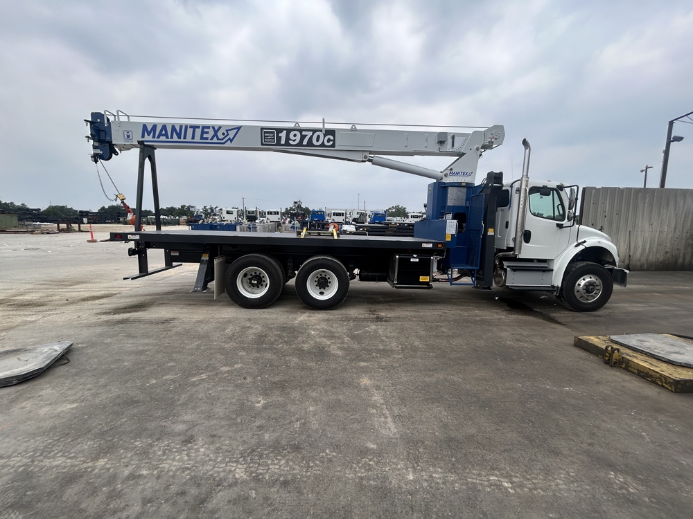
19 Ton (17,2 mton) Capacity
-
3-Section Proportional Boom 70'(21,3 m)
-
Fixed Jib Option 24’ (7,2 m)
-
2-Section Telescopic Jib Option 40' (12,2 m)
-
Self-Lubricating Boom Slider Pads
-
121' 3" (36,9 m) Maximum Tip Height
-
2-Speed Planetary Hoist with Grooved Drum and Negative Draft Flange
-
Radio Anti-Two Block System
-
Removable Boom Rest
-
Load Moment Indicator with Digital Display, CANbus Interface, Overload Shutdown and Internal Boom Length Cable
-
20' 10" (6,4 m) A-Frame Outriggers
-
10' (3 m) A-Frame Rear Stabilizers
-
Optional Front Bumper Stabilizer for 360° Area of Operation; equipped with FirstUp auto retract feature.
-
System Pressure Gauge
-
Clamp-On Mounting
-
Rugged, Weatherproof,Connectorized Electrical System. Circuit Status LED for LMI Option
-
Manitex UPTime Comprehensive Support
BOOM
Inverted T-cross section, 3-section telescoping type, extended and retracted proportionally by a double-acting hydraulic cylinder and cable-crowd system. Fitted with easily replaceable self-lubricated wear pads for smooth operation.
Model 1970C 3-Section 27’ 3-1/2” (8,3 m)
retracted to 70’ 0” (21,3 m) extended
Boom Point – Three non-metallic sheaves mounted on bronze bushings; removable pin-type rope guards.
Boom Elevation – Double-acting hydraulic cylinder. Working range from 10° below horizontal to 81° above.
Load Hook – 5-ton (4,5 mton) capacity hook with heavy-duty swivel and weight is provided for single-line operation.
HOIST
Maximum theoretical line speed 300 fpm (91 mpm). Maximum theoretical bottom-layer line pull 11,500 lb (5 216 kg). Two-speed planetary reducer with wet multi-disc spring applied, pressure-released internal brake and grooved drum; negative draft angle on drum flange to minimize line stacking while spooling.
Wire Rope – 300’ (91,4 m) of 9/16" (14,3 mm) diameter 6 x 19 EIPS IWRC.
SWING SYSTEM
Externally mounted, double-reduction planetary gearbox driven by hydraulic motor. Maximum swing speed 1.5 rpm. Wet multi-disc brake is spring-applied, pressure released. Ball-bearing swing circle with external gear. 372° non-continuous rotation is standard.
OUTRIGGERS
A-frame link type, operated independently for precise leveling. Equipped with double-acting hydraulic cylinders. 11-1/2” (292 mm) x 17-5/8” (448 mm) pivoting pads. Bubble level located near outrigger controls.
STABILIZERS
Rear Stabilizers – A-frame rigid design, clamp mounted under truck chassis by threaded rods and cross tube. Double-acting hydraulic cylinders operated independently for precise leveling. Fixed pad size 11-1/2” (292 mm) x 12-3/4” (324 mm) with flared leading edge.
Single Front Stabilizer (Option) – Mounted to truck frame at the front for 360° crane lifting operations. May require a full strength extended chassis depending on application, consult factory. Double acting hydraulic cylinder is equipped with an in-line relief valve to ensure proper float loading. Hydraulic circuit is operated from either operator station. First-up feature automatically retracts the front stabilizer when the outriggers or stabilizers are retracted for traveling.
MOUNTING
Pedestal and subframe are mounted to chassis by threaded rods and clamp plates. No welding, drilling or bolting to truck chassis is required.
Subframe – Torsion resistant, rigid 4-plate design mounted under crane, full length of truck frame.
Rear Underride Protection – Supplied on factory mounted cranes. Fabricated structure mounted at rear of carrier. Complies with Bureau of Motor Carrier Safety Standard 393.86.
Boom Rest – Heavy-duty fabrication. Easily removed to simplify loading and unloading truck deck.
CONTROL SYSTEM
Dual operator stations are equipped with four single-lever crane controls arranged in accordance with ANSI B30.5 standards. Fully proportional control valves. A system pressure gauge is mounted on the driver’s side console. Each station includes individual control levers for each outrigger and stabilizer for precise leveling. These control levers are shorter and positioned towards the center of the crane away from the main crane controls for added safety. Both control stations are equipped with engine start/stop, foot throttle, signal horn, boom angle indicator, load chart and range diagram.
HYDRAULICS
A 3-section pump direct-mounted to power take-off on truck transmission provides 32.4 gpm (123 lpm) to the hoist, 10 gpm (38 lpm) to the swing circuit and 20.6 gpm (78 lpm) to the remaining crane functions. A 70-gallon (265 liter) baffled hydraulic reservoir with strainer includes a 25- micron filter in the return line. Ball-type shutoff valve and strainer are provided in suction line. Use of SAE O-ring and face seal O-ring hydraulic fittings throughout system practically eliminates oil leaks.
Hydraulic Cylinders – All load-holding cylinders are equipped with integral holding valves.
WARNING SYSTEMS
Load Moment Indicator (LMI) – CANbus system maximize expansion capabilities. Sensors monitor boom hoist cylinder pressure, boom length and boom angle. Audio-visual indicators warn of impending overload conditions; overload shutoff feature prevents a continuous overload condition. Operator can monitor load conditions via display at the operator station, display mounting provided on both sides of the pedestal for easy access. Internal boom length sensing cable feature protects it from inadvertent damage in the field.
Radio Anti-Two-Block System – Audible warning and shutoff functions prevent hook from contacting boom point.
Back-Up Alarm – Electronic audible motion alarm activated when truck transmission is in reverse gear.
GENERAL
Electrical – State-of-the-art, weather-resistant components throughout. Environmentally sealed enclosure contains accessory circuit, terminal strips and relays. System is protected by a supplied in-line fuse. Designed to withstand high pressure washing and varying climates.
Design/Welding – Design conforms to ANSI B30.5. Welding conforms to AWS D1.1. Tested to SAE 1063 and SAE 765.
Manuals – Operator/maintenance and parts manuals depict correct crane operation, maintenance procedures and parts listing.
Warranty – 12-month warranty covers parts and labor resulting from defects in material and workmanship.
Note: In order to ensure continuous improvement, specifications may change without notice.

